3-43
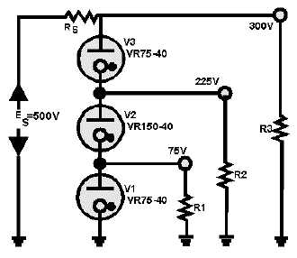
Figure 3-46.—VR tubes as voltage dividers
The current flowing through V2 in the figure is a combination of the current through R1 and the
current through V1. The current through V3, on the other hand, is the sum of the currents through V2 and
R2. Since V3 has more current flowing through it than any of the other VR tubes, it places or determines
the limit on the maximum current in the VR tube circuit. Since the maximum rating of V3 is 40
milliamperes, the currents through R1 and R2 must be limited to only a few milliamperes, or the rating of
V3 will be exceeded and regulation will cease.
The obvious advantage in using VR tubes in series is to provide several regulated voltages from a
single power supply. The primary disadvantage is in the current limitations. Since it is impossible to have
all VR tubes operating about their mean current values, this limits the ability of the circuit to regulate over
wide ranges of variations in load resistance or source voltage.
VR Tubes Connected in Parallel
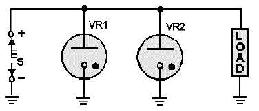
One might expect that connecting VR tubes in parallel as shown in figure 3-47 would increase the
current handling capacity of the network. Although this is true for some gas-filled tubes, it is not true for
VR tubes. In figure 3-47, two VR tubes are constructed in exactly the same way. The only difference will
be a slight variation in their ionization potential. For the purpose of this discussion, VR tube VR1 will
have a lower ionization potential than VR2. The potential that must be reached before a VR tube ionizes
is considerably higher than its normal operating voltage.
Figure 3-47.—VR tubes connected in parallel.


