5-5
modulation peak; specifically, both positive-peak and negative-peak overmodulation must be indicated.
Positive-peak overmodulation occurs when the positive modulation exceeds 100%; negative-peak
overmodulation occurs when the negative modulation exceeds 100%.
Oscilloscope Measurement Methods
The oscilloscope is widely used as an amplitude-modulation monitor and measuring instrument.
Since it is capable of presenting visual indications of the modulated output of AM transmitters, the
oscilloscope is reliable for detecting overmodulation and determining the percentage of modulation. For
example, the relative error of most measurements taken with a 5-inch crt is about 10%. Although such
accuracy is adequate for many maintenance checks, the oscilloscope is usually considered more valuable
as a monitor of general modulation conditions. It is also used to monitor the amplitude-modulated output
of a radio transmitter when photographic records are desired.
Types of Modulation Display
Two types of modulation patterns are provided by the oscilloscope, depending upon the hookup
used. These patterns are the WAVE-ENVELOPE PATTERNS, as shown in figures 5-2 and 5-3, and the
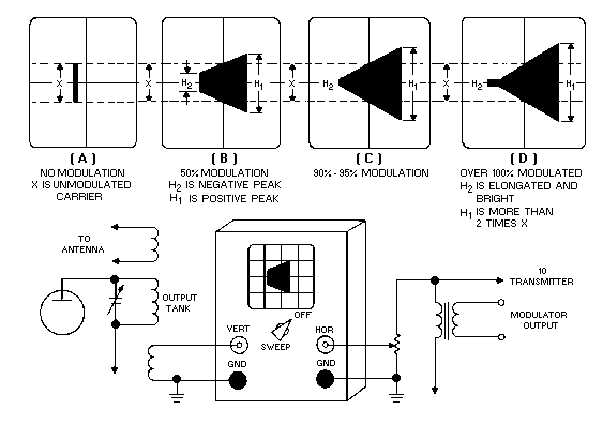
TRAPEZOIDAL PATTERN, as shown in figure 5-4.
Figure 5-4.—Trapezoidal modulation patterns.
Figure 5-2 shows an oscilloscope presentation of an rf carrier that is amplitude-modulated by a
complex wave, such as that of speech. Figures 5-4 and 5-5 show the effects of over 100% modulation on
the carrier wave. The carrier wave envelope pattern (as shown in fig. 5-3) is obtained by applying the rf-