1-42
AM TRANSMITTER PRINCIPLES
In this section we will describe the methods used to apply voice signals (intelligence) to a carrier
wave by the process of amplitude modulation (AM).
An AM transmitter can be divided into two major sections according to the frequencies at which they
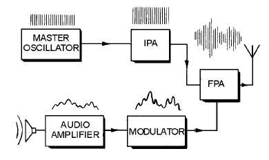
operate, radio-frequency (rf) and audio-frequency (af) units. The rf unit is the section of the transmitter
used to generate the rf carrier wave. As illustrated in figure 1-37, the carrier originates in the master
oscillator stage where it is generated as a constant-amplitude, constant-frequency sine wave. The carrier is
not of sufficient amplitude and must be amplified in one or more stages before it attains the high power
required by the antenna. With the exception of the last stage, the amplifiers between the oscillator and the
antenna are called INTERMEDIATE POWER AMPLIFIERS (ipa). The final stage, which connects to the
antenna, is called the FINAL POWER AMPLIFIER (fpa).
Figure 1-37.—Block diagram of an AM transmitter.
The second section of the transmitter contains the audio circuitry. This section of the transmitter
takes the small signal from the microphone and increases its amplitude to the amount necessary to fully
modulate the carrier. The last audio stage is the MODULATOR. It applies its signal to the carrier in the
final power amplifier. In this way, intelligence is included in the radiated rf waveform.
The Modulated Wave
The frequencies present in a signal can be conveniently represented by a graph of the frequency
spectrum, shown in figure 1-38. In this graph, each individual frequency is portrayed as a vertical line.
The position of the line along the horizontal axis indicates the frequency of the signal. The height of the
frequency line is proportional to the amplitude of the signal. The rf spectrum in figure 1-38 shows the
frequencies present when heterodyning occurs between frequencies of 5 and 100 kilohertz.

