3-36
scanning drum in the receiver. This ensures proper phasing with respect to the starting position of the
scanning drum in the transmitter.
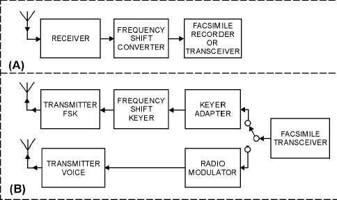
Figure 3-33 is a block diagram of the equipment necessary for radio facsimile operation. View A
shows the receiving system. This system consists of a standard radio receiver, a frequency-shift converter,
and a facsimile recorder. View B shows two systems for transmitting TIF signals. The upper row of
blocks is for carrier-frequency shift transmission. This system consists of a facsimile transceiver, a keyer
adapter, a frequency shift keyer and a transmitter capable of fsk emission. The lower row of blocks is for
audio-frequency shift transmission and uses a fax transceiver, a radio modulator, and an AM transmitter.
Figure 3-33.—Radio facsimile systems.
SECURITY, QUALITY MONITORING, AND SAFETY
Security, quality monitoring, and safety are important areas that you must be aware of. If the
fundamentals are followed, you will see higher quality communications. You will also help meet the
communications goals of the Navy. Let's find out what these fundamentals are and what they will do for
you.
TEMPEST
Compromising emanations (ce) are, generally referred to as TEMPEST. These signals may be
unintentional, data-related, or intelligence-bearing. If intercepted or analyzed, these signals could disclose
classified information. TEMPEST problems are associated with material transmitted, received, handled,
or otherwise processed by electrical information processing equipment or systems. Any electrical
information processing device may cause problems. Even your electric typewriter or a large, complex
data processor may emit interceptable compromising emanations. Some countermeasures taken to ensure
against TEMPEST problems are listed below:


