1-71
The TX-TDX-TR SYSTEM performs subtraction when the system contains standard synchro
connections. Addition can also be performed with this system by reversing the S1 and S3 leads between
the TX and the TDX, and the R1 and R3 leads between the TDX and the TR. Remember, this system
works like a basic synchro system when the rotor of the TDX is on 0º; in this condition the TR rotor
follows the TX rotor exactly.
The TX-TDR-TX SYSTEM performs subtraction when the system contains standard synchro
connections. Addition can also be performed with this system when the R1 and R3 leads between the
TDR rotor and TX No. 2 are reversed.
CONTROL SYNCHRO SYSTEMS contain control synchros and are used to control large amounts
of power with a high degree of accuracy. These synchro systems control servos that generate the required
power to move heavy loads.
CONTROL SYNCHROS are of three different types: the control transmitter (CX), the control
transformer (CT), and the control differential transmitter (CDX). The CX and the CDX are identical to the
TX and the TDX except for higher impedance windings. In theory, the CX and CDX are the same as the
TX and TDX, respectively.
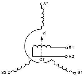
The CONTROL TRANSFORMER (CT) is a synchro device that compares two signals, the
electrical signal applied to its stator, and the mechanical signal applied to its rotor. The output is an
electrical voltage, which is taken from the rotor winding and used to control some form of power
amplifying device. The phase and amplitude of the output voltage depend on the angular position of the
rotor with respect to the magnetic field of the stator.
ERROR SIGNAL is the name given to the electrical output of a CT. The reason is that the electrical
output voltage represents the amount and direction that the CX and CT rotors are out of correspondence.
It is this error signal that eventually is used in moving the load in a typical servo system.