2-5
The mechanical linkage attached to the servo motor also moves the rotor of the CT. This feedback
causes the amplitude of the error signal to decrease, slowing the speed at which the load is moving.
In view D, the servo motor has driven both the load and the rotor of the CT, so that the CT is now in
correspondence with the CX rotor. As a result, the error signal is reduced to zero (nulled). The load stops
at its new position. Note that in this servo system, we moved a heavy load to a predetermined position
through the simple turning of a handcrank. In responding to the handcrank, the servo system performed a
basic positioning function.
Two key points for you to remember, thus far, about the operation of the closed-loop servo system
are:
1. The original error (movement of the CX rotor) was "detected" by the CT. For this reason the CT
is called an ERROR DETECTOR.
2. The servo motor, in addition to moving the load, also provides mechanical feedback to the CT to
reduce the error signal. For this reason the servo motor is also called an ERROR REDUCER.
Q-4. An error signal is the difference between what two quantities fed to the CT (error detector)?
Q-5. What are the two functions of the servo motor in the system shown in figure 2-2?
FUNCTIONAL SERVO LOOPS
Servo systems are also classified according to their functions: POSITION, VELOCITY, and
ACCELERATION. We will cover the most common, POSITION and VELOCITY, in detail.
The Position Servo Loop
The primary purpose of the POSITION SERVO is to control the position of the load it is driving. It
can be used to position a great number of devices (for example, valves, control surfaces, weapons, etc.).
The basic servo loop we just explained using the block diagram in figure 2-2 is that of an ac position
servo system. In the ac position servo system, the amplitude and phase of the ac error signal determine the
amount and direction the load will be driven.
In a dc position servo system, the amplitude and polarity of a dc error signal respectively are used to
determine the amount and direction the load will be driven.
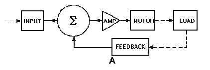
Figure 2-3, view A, is a block diagram of a closed-loop de position servo. Note the Greek letter
Sigma (!), meaning summation, surrounded by a circle.
Figure 2-3A.—Block diagram of a position servo.
This is the summation, or "sum point" where the input signal, and the response signal (feedback) are
summed to produce the error signal.


