2-8
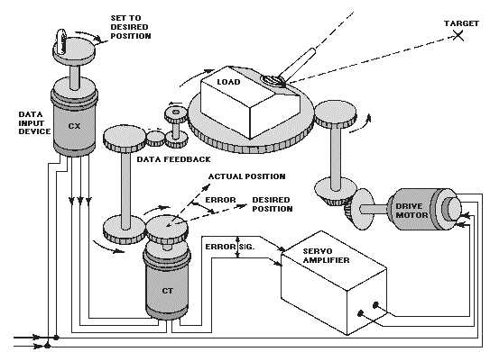
desired position. As the turret moves, mechanical feedback turns the CT rotor toward agreement with the
CX rotor. As the load approaches the proper position, less and less power is supplied to the motor because
of the decreasing error voltage developed in the CT. When the electrical position of the CT rotor agrees
with the position of the CX rotor, the error voltage reaches zero and power is removed from the motor.
The turret is now in the desired position.
Figure 2-5.—Typical position servo.
In the actual system, the heavy gun turret's momentum tends to carry it past the desired position.
This overshoot causes the rotor of the CT to move out of correspondence with the CX rotor. This, in turn,
develops a new error signal that is opposite in polarity to the original input signal. The new error signal
causes the turret to drive back toward the desired position — but the turret's momentum once again causes
an overshoot, making the system drive in the opposite direction again. If this oscillation of the load
around the desired position is allowed to go unchecked, a condition known as HUNTING results. Figure
2-6 shows graphically the result of a series of overtravels of the correspondence point (hunting). In most
servos an electronic network known as an ANTIHUNT or DAMPING system is used to minimize this
undesirable effect. We will cover antihunt and damping systems in depth later in this chapter.