2-7
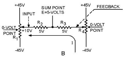
Figure 2-4B.—Development of the error signal.
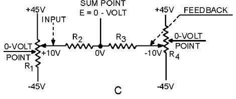
Figure 2-4C.—Development of the error signal.
The +5 volt error signal is fed into the amplifier. The amplified output starts driving the motor. The
mechanical feedback from the motor drives the R4 wiper arm down when the R1 wiper is moved up, as
shown in view C. This causes the right-hand side of R3 to go negative. When the R
4
wiper travels far
enough toward negative, it causes the right-hand side of R3 to equal the voltage, but of opposite polarity,
of the left-hand side of R2. Simply stated, the voltage at the sum point will be zero again, and the motor
will stop. This is true because R2 and R
3
are of equal ohmic value, and when the left-hand side equals +10
volts, the right-hand side equals -10 volts. The point between the two resistors becomes zero volts at this
time. At the instant that this occurs, the output shaft will have positioned the load to the new position.
Figure 2-5 shows the basic operation of a typical position servo having wide application in Navy
equipment. Remember that in a position servo, an input order indicates a position in which a load is to be
placed. The load in figure 2-5 is a gun turret. The purpose of the system is to position the gun by means of
an order from a remote handcrank. The load is mechanically coupled through a gear train to the rotor of a
CT so that the turret's position is always accurately represented by the position of the CT's rotor. An order
signaling the desired position of the gun turret is fed into the servo by positioning the rotor of the CX with
the handcrank. A corresponding signal immediately appears across the CT stator. This signal differs from
the actual position of the gun turret, causing an error voltage to be developed across the CT rotor. The
error voltage is fed from the CT rotor to the servo amplifier. At this point it is converted into power with a
polarity or phase relationship that drives the motor in the direction necessary to bring the load into the