3-3
Digital equipment must be capable of many more operations than those described in chapter 2.
Provisions must be made for accepting information; performing arithmetic or logic operations; and
transferring, storing, and outputting information. Timing circuits are included to ensure that all operations
occur at the proper time.
In this chapter you will become acquainted with the logic circuits used to perform the operations
mentioned above.
THE EXCLUSIVE OR GATE
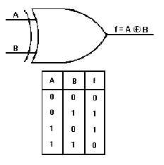
The exclusive OR gate is a modified OR gate that produces a HIGH output when only one of the
inputs is HIGH. You will often see the abbreviation X-OR used to identify this gate. When both inputs
are HIGH or when both inputs are LOW, the output is LOW.
The standard symbol for an exclusive OR gate is shown in figure 3-2 along with the associated Truth
Table. The operation function sign for the exclusive OR gate is .
Figure 3-2. —Exclusive OR gate and Truth Table.
If you were to observe the input and output signals of an X-OR gate, the results would be similar to
those shown in figure 3-3. At T0, both inputs are LOW and the output is LOW. At T1, A goes to HIGH
and remains HIGH until T2. During this time the output is HIGH. At T3, B goes HIGH and remains HIGH
through T5. At T4, A again goes HIGH and remains HIGH through T5. Between T3and T4 , the output is
HIGH. At T4, when both A and B are HIGH, the output goes LOW.


