3-15
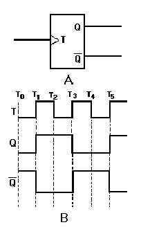
Figure 3-15. —Toggle (T) flip-flop: A. Standard symbol; B. Timing diagram.
The timing diagram in figure 3-15, view B, shows the toggle input and the resulting outputs. We will
assume an initial condition (T0) of Q being LOW and Q being HIGH. At T1, the toggle changes from a
LOW to a HIGH and the device changes state; Q goes HIGH and Q goes LOW. The outputs remain the
same at T2 since the device is switched only by a LOW-to-HIGH transition. At T3, when the toggle goes
HIGH, Q goes LOW and Q goes HIGH; they remain that way until T5.
Between T1 and T5, two complete cycles of T occur. During the same time period, only one cycle is
observed for Q or Q . Since the output cycle is one-half the input cycle, this device can be used to divide
the input by 2.
The most commonly used T FFs are J-K FFs wired to perform a toggle function. This use will be
demonstrated later in this section.
Q22. How many inputs does a T FF have?
Q23. What is the purpose of using T FFs?
D FLIP-FLOP
The D FF is a two-input FF. The inputs are the data (D) input and a clock (CLK) input. The clock is
a timing pulse generated by the equipment to control operations. The D FF is used to store data at a
predetermined time and hold it until it is needed. This circuit is sometimes called a delay FF. In other
words, the data input is delayed up to one clock pulse before it is seen in the output.
The simplest form of a D FF is shown in figure 3-16, view A. Now, follow the explanation of the
circuit using the Truth Table and the timing diagram shown in figure 3-16, views B and C.