3-12
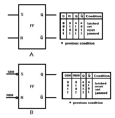
Figure 3-12. —R-S flip-flop: A. Standard symbol; B. R-S FF with inverted inputs.
The R-S FF has two output conditions. When the Q output is HIGH and Q is LOW, the FF is set.
When Q is LOW and Q is HIGH, the FF is reset. When the R and S inputs are both LOW, the Q and Q
outputs will both be HIGH. When this condition exists, the FF is considered to be JAMMED and the
outputs cannot be used. The jammed condition is corrected when either S or R goes HIGH.
To set the flip-flop requires a HIGH on the S input and a LOW on the R input. To reset, the opposite
is required; S input LOW and R input HIGH. When both R and S are HIGH, the FF will hold or "latch"
the condition that existed before both inputs went HIGH.
Because the S input of this FF requires a logic LOW to set, a more easily understood symbol is
shown in figure 3-12, view B. Refer to this view while reading the following paragraph.
In our description of R-S FF operation, let’s assume that the signals applied to the S and R inputs are
the LSDs of two different binary numbers. Let’s also assume that these two binary numbers represent the
speed and range of a target ship. The LSDs will be called SB0 (Speed Bit 0) and RB0 (Range Bit 0) and
will be applied to the S and R inputs respectively. Refer to figure 3-12, view B, and figure 3-13. At time
T0, both SB0 and RB0 are HIGH, as a result, both Q and Q are HIGH. This is the jammed state and as
mentioned earlier, cannot be used in logic circuitry. At T1, SB0 goes LOW and RB0 remains HIGH; Q
goes LOW and Q remains HIGH; the FF is reset. At T2 RB0 goes LOW and SB0 remains LOW; the FF
is latched in the reset condition. At T3, SB0 goes HIGH and RB0 remains LOW; the FF sets. At T4 SB0
goes LOW and RB0 goes HIGH; the FF resets. When SB0 and RB0 input conditions reverse at T5, the FF
sets. The circuit is put in the latch condition at T6 when SB0 goes LOW. Notice that the output changes
states ONLY when the inputs are in opposite states.