2-16
METHODS OF FREQUENCY MODULATION.—The circuit shown earlier in figure 2-6 and the
discussion in previous paragraphs were for illustrative purposes only. In reality, such a circuit would not
be practical. However, the basic principle involved (the change in reactance of an oscillator circuit in
accordance with the modulating voltage) constitutes one of the methods of developing a frequency-
modulated wave.
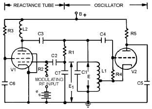
Reactance-Tube Modulation.—In direct modulation, an oscillator is frequency modulated by a
REACTANCE TUBE that is in parallel (SHUNT) with the oscillator tank circuit. (The terms "shunt" or
"shunting" will be used in this module to mean the same as "parallel" or "to place in parallel with"
components.) This is illustrated in figure 2-11. The oscillator is a conventional Hartley circuit with the
reactance-tube circuit in parallel with the tank circuit of the oscillator tube. The reactance tube is an
ordinary pentode. It is made to act either capacitively or inductively; that is, its grid is excited with a
voltage which either leads or lags the oscillator voltage by 90 degrees.
Figure 2-11.—Reactance-tube fm modulator.
When the reactance tube is connected across the tank circuit with no modulating voltage applied, it
will affect the frequency of the oscillator. The voltage across the oscillator tank circuit (L1 and C1) is also
in parallel with the series network of R1 and C7. This voltage causes a current flow through R1 and C7. If
R1 is at least five times larger than the capacitive reactance of C7, this branch of the circuit will be
essentially resistive. Voltage E
1, which is across C7, will lag current by 90 degrees. E
1
is applied to the
control grid of reactance tube V1. This changes plate current (Ip), which essentially flows only through
the LC tank circuit. This is because the value of R1 is high compared to the impedance of the tank circuit.
Since current is inversely proportional to impedance, most of the plate current coupled through C3 flows
through the tank circuit.
At resonance, the voltage and current in the tank circuit are in phase. Because E1 lags E by 90
degrees and I
is in phase with grid voltage E1, the superimposed current through the tank circuit lags the
original tank current by 90 degrees. Both the resultant current (caused by Ip) and the tank current lag tank
voltage and current by some angle depending on the relative amplitudes of the two currents. Because this
resultant current is a lagging current, the impedance across the tank circuit cannot be at its maximum
unless something happens within the tank to bring current and voltage into phase. Therefore, this situation
continues until the frequency of oscillations in the tank circuit changes sufficiently so that the voltages
across the tank and the current flowing into it are again in phase. This action is the same as would be
produced by adding a reactance in parallel with the L1C1 tank. Because the superimposed current lags
voltage E by 90 degrees, the introduced reactance is inductive. In NEETS, Module 2, Introduction to