1-36
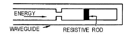
Figure 1-45B.—Terminating waveguides.
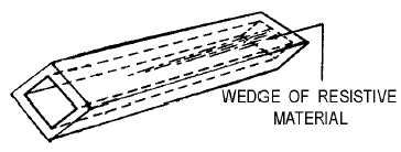
Figure 1-45C.—Terminating waveguides.
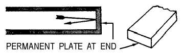
Figure 1-45D.—Terminating waveguides.
Still another method for terminating a waveguide is the use of a wedge of highly resistive material,
as shown in of figure 1-45C. The plane of the wedge is placed perpendicular to the magnetic lines of
force. When the H lines cut through the wedge, current flows in the wedge and causes a power loss. As
with the other methods, this loss is in the form of heat. Since very little energy reaches the end of the
waveguide, reflections are minimum.
All of the terminations discussed so far are designed to radiate or absorb the energy without
reflections. In many instances, however, all of the energy must be reflected from the end of the
waveguide. The best way to accomplish this is to permanently weld a metal plate at the end of the
waveguide, as shown in figure 1-45D.
Q-37. What device is used to produce a gradual change in impedance at the end of a waveguide?
Q-38. When a waveguide is terminated in a resistive load, the load must be matched to what property of
the waveguide?
Q-39. What is the primary purpose of a dummy load?
Q-40. The energy dissipated by a resistive load is most often in what form?