1-20
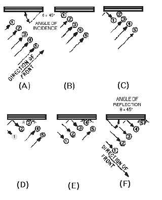
Figure 1-26.—Reflection of a single wavefront.
Figures 1-27A and 1-27B, each illustrate the direction of propagation of two different
electromagnetic wavefronts of different frequencies being radiated into a waveguide by a probe. Note that
only the direction of propagation is indicated by the lines and arrowheads. The wavefronts are at right
angles to the direction of propagation. The angle of incidence (") and the angle of reflection (ø) of the
wavefronts vary in size with the frequency of the input energy, but the angles of reflection are equal to
each other in a waveguide. The CUTOFF FREQUENCY in a waveguide is a frequency that would cause
angles of incidence and reflection to be zero degrees. At any frequency below the cutoff frequency, the
wavefronts will be reflected back and forth across the guide (setting up standing waves) and no energy
will be conducted down the waveguide.