1-14
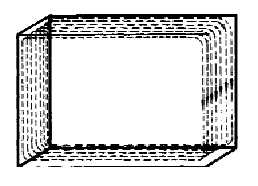
Figure 1-16B.—Magnetic fields on a two-wire line with half-wave frames.
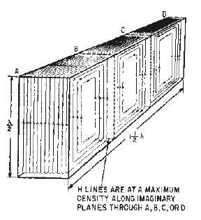
If the two-wire line and the half-wave frames are developed into a waveguide that is closed at both
ends (as shown in figure 1-16B), the distribution of H lines will be as shown in figure 1-17. If the
waveguide is extended to 1 1/2!, these H lines form complete loops at half-wave intervals with each
group reversed in direction. Again, no H lines can form outside the waveguide as long as it is completely
enclosed.
Figure 1-17.—Magnetic field pattern in a waveguide.
Figure 1-18 shows a cross-sectional view of the magnetic field pattern illustrated in figure 1-17. Note
in view (A) that the field is strongest at the edges of the waveguide where the current is highest. The
minimum field strength occurs at the zero-current points. View (B) shows the field pattern as it appears
!/4 from the end view of the waveguide. As with the previously discussed E fields, the H fields shown in
figures 1-17 and 1-18 represent a condition that exists at only one instant in time. During the peak of the
next half cycle of the input current, all field directions are reversed and the field will continue to change
with changes in the input.