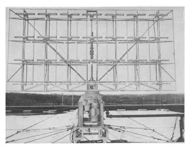
3-15
Figure 3-15.—Bedspring array.
FREQUENCY-SENSITIVE ANTENNA
The radar antenna in figure 3-16 uses a feed section to drive horizontally stacked array sections
which radiate the applied rf pulses. The same array sections receive the target returns. Each array contains
slots cut to radiate and receive a particular frequency. Bearing data is obtained by mechanically rotating
the antenna 360 degrees. Elevation data is obtained by electronic scanning of the beam in elevation. The
radar antenna is frequency sensitive and radiates pulses at an elevation angle determined by the applied
frequency. When the frequency is increased, the beam elevation angle decreases. Conversely, when the
applied frequency is decreased, the beam elevation angle increases. The beam elevation angle is therefore
selected by the application of a frequency corresponding to the desired angle of elevation. The physical
length of the antenna feed section, called the SERPENTINE SECTION (figure 3-17), in relation to the
wavelength of the applied energy determines the direction of the radiated beam. You may understand this
more clearly if you consider how the beam is shifted. The shift occurs with a change in frequency because
the positive and negative peaks of the energy arrive at adjacent slotted arrays at different times. The
change in the field pattern is such that the angle of departure (angle at which the radiated beam leaves the
antenna) of the beam is changed. Note that a change in phase of the applied rf energy would cause the
same effect.