3-13
ANTENNA ARRAYS
Sharply directive antennas can be constructed from two or more simple half-wave dipole elements.
They must be positioned so that the fields from the elements add in some directions and cancel in others.
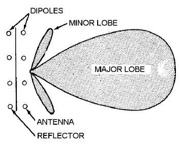
Such a set of antenna elements is called an ANTENNA ARRAY. When a reflector is placed behind the
dipole array, radiation occurs in one direction with a pattern similar to the one shown in figure 3-13.
Figure 3-13.—Field pattern of an antenna array.
You will encounter two basic types of antenna arrays, PARASITIC and DRIVEN. Both types of
antenna arrays were explained in NEETS, Module 10, Introduction to Wave Propagation, Transmission
Lines, and Antennas. Only a brief review is presented in this chapter.
The parabolic reflector antennas previously discussed and the antenna shown in figure 3-13 are
examples of parasitic arrays. Notice that the reflector in figure 3-13 is not directly connected to the energy
source. Driven arrays, in which all the radiating elements are connected to the energy source, have
smaller losses than parasitic arrays while retaining some of the narrow-beam characteristics. Parasitic
arrays, such as the parabolic reflector, are used primarily as antennas in fire control radars and other
installations, such as microwave communication systems, that require very accurate (narrow) beams.
Driven arrays are used primarily as search-radar antennas because extremely narrow beams are less
critical than low losses.
If you position a number of driven half-wave antenna elements with respect to each other so that
energy from the individual elements will add in certain directions and cancel in other directions, then the
antenna system is directional.
Signals from a number of different sources may contribute to or subtract from the overall effect. By
properly phasing the energy fed to the antenna elements, and by properly locating the elements, you can
control the direction of the energy. You can cause the energy to add in the desired direction and to be out
of phase (cancel) in the undesired direction.
Driven arrays are usually made up of a number of half-wave dipoles positioned and phased so that
the desired directional pattern will be achieved. Figure 3-14, view (A), shows a simple antenna array

