3-21
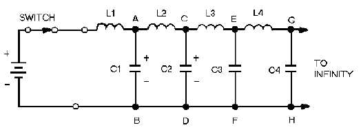
Figure 3-20.—Dc applied to an equivalent transmission line.
As the switch is closed, the battery voltage is applied to the input terminals of the line. Now, C1 has
no charge and appears, effectively, as a short circuit across points A and B. The full battery voltage
appears across inductor L1. Inductor L1 opposes the change of current (0 now) and limits the rate of
charge of C1.
Capacitor C2 cannot begin to charge until after C1 has charged. No current can flow beyond points
A and B until C1 has acquired some charge. As the voltage across C1 increases, current through L2 and
C2 charges C2. This action continues down the line and charges each capacitor, in turn, to the battery
voltage. Thus a voltage wave is traveling along the line. Beyond the wavefront, the line is uncharged.
Since the line is infinitely long, there will always be more capacitors to be charged, and current will not
stop flowing. Thus current will flow indefinitely in the line.
Notice that current flows to charge the capacitors along the line. The flow of current is not advanced
along the line until a voltage is developed across each preceding capacitor. In this manner voltage and
current move down the line together in phase.
Ac Applied to an Infinite Line
An rf line displays similar characteristics when an ac voltage is applied to its sending end or input
terminals. In figure 3-21, view A, an ac voltage is applied to the line represented by the circuit shown.