3-17
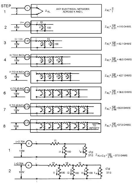
Figure 3-17.—Termination of a line.
In figure 3-17, resistors were used to show impedance characteristics for the sake of simplicity.
Figuring the actual impedance of a line having reactance is very similar, with inductance taking the place
of the series resistors and capacitance taking the place of the shunt resistors. The characteristic impedance
of lines in actual use normally lies between 50 and 600 ohms.
When a transmission line is "short” compared to the length of the radio-frequency waves it carries,
the opposition presented to the input terminals is determined primarily by the load impedance. A small
amount of power is dissipated in overcoming the resistance of the line. However, when the line is "long”
and the load is an incorrect impedance, the voltages necessary to drive a given amount of current through
the line cannot be accounted for by considering just the impedance of the load in series with the