3-32
Figure 3-38B.—Series RC circuit.
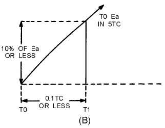
However, during the first 10 percent of the first time constant, the rate of voltage change across the
capacitor is almost constant (linear). Suppose that S1 is placed in position P at T0, and C is allowed to
charge for 0.1 time constant. This is shown as T0 to T1 in view (B). Notice that the rate of voltage change
across C is nearly constant between T0 and T1. Now, assume that at T1 the switch is moved from position
P to position Q. This shorts the capacitor, and it discharges very rapidly. If the switch is placed back in
position P, the capacitor will start charging again.
By selecting the sizes of R and C, you can have a time constant of any value you desire. Further, by
controlling the time S1 remains closed, you can generate a sawtooth of any duration. Figure 3-39 is the
Universal Time Constant Chart. Notice in the chart that if 1 time constant is 1,000 microseconds, S1
(figure 3-38, view (A )) can be closed no longer than 100 microseconds to obtain a reasonable linear
sawtooth. In this example, C1 will charge to nearly 10 volts in 0.1 time constant.