3-33
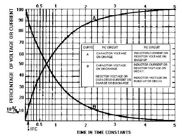
Figure 3-39.—Universal Time Constant Chart.
The dimensions of the sawtooth waveform used in oscilloscopes need to be discussed before going
any further. Figure 3-40 shows a sawtooth waveform with the various dimensions labeled. The duration
of the rise of voltage (T0 to T1) is known as the SWEEP TIME or ELECTRICAL LENGTH. The
electron beam of an oscilloscope moves across the face of the cathode ray tube during this sweep time.
The amount of voltage rise per unit of time is referred to as the SLOPE of the waveform. The time from
T1 to T2 is the capacitor discharge time and is known as FALL TIME or FLYBACK TIME. This
discharge time is known as flyback time because during this period the electron beam returns, or "flys"
back, from the end of a scanning line to begin the next line.