4
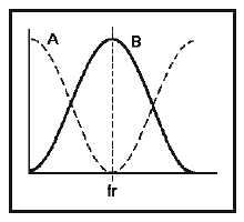
Figure 1B.—Series-resonant circuit curves.
IN ANSWERING QUESTIONS 1-22 AND
1-23, REFER TO FIGURE 1B.
1-22. Response curve B for a series-resonant
circuit represents which of the following
circuit characteristics?
1. Power
2. Voltage
3. Current
4. Impedance
1-23. At resonance, which of the following
series-resonant circuit values is at a
maximum value?
1. Circuit current
2. Voltage across L
3. Voltage across C
4. Circuit impedance
1-24. In a series-resonant circuit operating at fr,
what term describes the impedance of the
circuit?
1. Resistive
2. Inductive only
3. Capacitive only
4. Capacitive-inductive
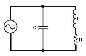
Figure 1C.—Parallel-resonant circuit.
IN ANSWERING QUESTIONS 1-25
THROUGH 1-27, REFER TO FIGURE 1C.
1-25. In the parallel-resonant circuit, what is
the phase relationship between the
current in the inductor and the current in
the capacitor?
1. Inductor current is in phase with
capacitor current
2. Inductor current is 45 degrees out of
phase with capacitor current
3. Inductor current is 90 degrees out of
phase with capacitor current
4. Inductor current is 180 degrees out of
phase with capacitor current
1-26. In the parallel-resonant circuit, what is
the phase relationship between voltage in
the inductor and the voltage in the
capacitor.
1. Inductor voltage is in phase with
capacitor voltage
2. Inductor voltage is 45 degrees out of
phase with capacitor voltage
3. Inductor voltage is 90 degrees out of
phase with capacitor voltage
4. Inductor voltage is 180 degrees out of
phase with capacitor voltage