• Home
  • Download PDF
  • Order CD-ROM
  • Order in Print
THE TWO-INPUT, SINGLE-OUTPUT, DIFFERENCE AMPLIFIER - 14180_92
THE TWO-INPUT, SINGLE-OUTPUT, DIFFERENCE AMPLIFIER - 14180_94

Neets Module 08-Introduction to Amplifiers
Page Navigation
  75    76    77    78    79  80  81    82    83    84    85  
3-5 
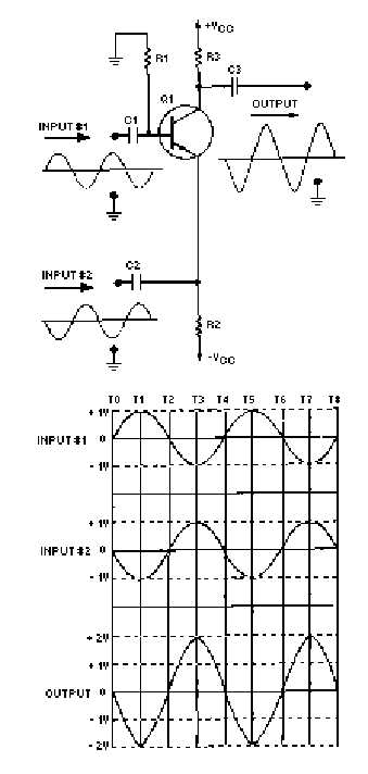
Figure 3-3.—Input signals 180º  out of phase. The circuit and the input and output signals are shown at the top of the figure. The lower portion of the figure is a comparison of the input signals and the output signal. Notice the vertical lines marked "T0" through "T8." These represent "time zero" through "time eight." In other words, these lines provide a way to examine the two input signals and the output signal at various instants of time.


Western Governors University

Privacy Statement
Press Release
Contact

© Copyright Integrated Publishing, Inc.. All Rights Reserved. Design by Strategico.