3-9
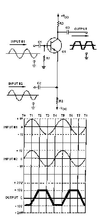
Figure 3-5.—Input signals 90º out of phase.
This +1-volt bias signal causes the output signal to be -10 volts at time zero (T0). Between time zero
(T0) and time one (T1), both input signals go positive. The difference between the input signals stays
constant. The effect of this is to keep the bias at +1 volt for the entire time between T0 and T1. This, in
turn, keeps the output signal at -10 volts.
Between time one (T1) and time two (T2), input signal number one goes in a negative direction but
input signal number two continues to go positive. Now the difference between the input signals decreases