2-10
Figure 2-4B.—Amplifiers showing reactive elements and reactance.
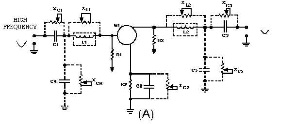
The actual circuit components are: C1, C2, C3, R1, R2, R3, and Q1. C1 is used to couple the input
signal. R1 develops the input signal. R2, the emitter resistor, is used for proper biasing and temperature
stability. C2 is a decoupling capacitor for R2. R3 develops the output signal. C3 couples the output signal
to the next stage. Q1 is the amplifying device.
The phantom circuit elements representing the capacitance and inductance of the wiring are: L1, L2,
C4, and C5. L1 represents the inductance of the input wiring. L2 represents the inductance of the output
wiring. C4 represents the capacitance of the input wiring. C5 represents the capacitance of the output
wiring.
In view (A) the circuit is shown with a low-frequency input signal. Since the formulas for capacitive
reactance and inductive reactance are:
You should remember that if frequency is low, capacitive reactance will be high and inductive reactance
will be low. This is shown by the position of the variable resistors that represent the reactances. Notice
that XL1 and XL2 are low; therefore, they do not "drop" very much of the input and output signals. XC4
and XC5 are high; these reactances tend to "block" the input and output signals and keep them from going
to the power supplies (VBB and VCC). Notice that the output signal is larger in amplitude than the input
signal.
Now look at view (B). The input signal is a high-frequency signal. Now XC is low and XL is high.
XL1 and XL2 now drop part of the input and output signals. At the same time XC4 and XC5 tend to "short"
or "pass" the input and output signals to signal ground. The net effect is that both the input and output
signals are reduced. Notice that the output signal is smaller in amplitude than the input signal.
Now you can see how the capacitance and inductance of the wiring affect an amplifier, causing the
output of an amplifier to be less for high-frequency signals than for low-frequency signals.