3-9
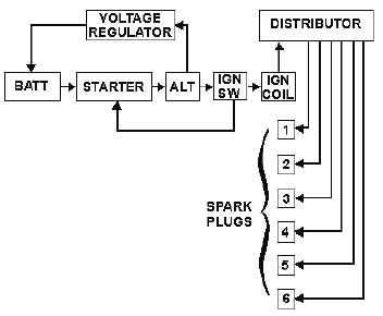
Figure 3-8.—Block diagram.
The battery is the initial source of power for the starter and ignition systems. The starter is turned by
power from the battery when the ignition switch is turned to the START position. Power is also supplied,
through the ignition switch, to the coil. From the coil, power is supplied to the distributor and finally to
the spark plugs for ignition.
Once the engine is running, the starter is no longer required. The running engine acts as the prime
mover for the alternator. (This is accomplished through a belt and pulley system attached to the engine's
crankshaft.) The alternator now takes over as the power supplier for the ignition system. It supplies power
through the ignition switch to the coil, from the coil to the distributor, and finally from the distributor to
the spark plugs. At the same time, the alternator supplies power back through the voltage regulator to the
battery for charging purposes. This completes the cycle until the engine is shut down and started again.
Note that the engine is not shown in the block diagram as the prime mover for the alternator. The
engine is a mechanical rather than an electrical function. The illustrated block diagram is of the electrical
system only. There are block diagrams that show strictly mechanical components or both mechanical and
electrical components.
SINGLE-LINE DIAGRAM
The single-line diagram is used basically for the same purpose as the block diagram. When used with
text material, it gives you a basic understanding of the functions of the components of a system.
There are two major differences between the single-line diagram and the block diagram. The first
difference is that the single-line diagram uses symbols, rather than labeled blocks, to represent
components. Second, the single-line diagram shows all components in a single line (figure 3-9). There are
no interconnections shown for selected components as were shown on the block diagram (for example,
alternator to voltage regulator and back to the battery). The single-line diagram is very simplified and
should be used primarily to learn (in very broad terms) the function of each of the various components as
a part of the total system.