3-6
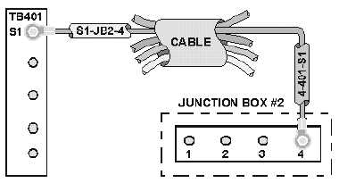
Figure 3-5.—Marking of conductors running to a junction box.
POWER TOOL AND APPLIANCE MARKING SYSTEMS
As with the wire- and cable-numbering systems discussed so far, there are many color-coding
systems used in electrical and electronic applications. The color-coding system discussed here is the one
used to code conductors for power tools and appliances.
An electrical power tool or appliance is required to have a three-wire cable. The conductors in the
cable are color-coded black, white, and green. At shore bases or civilian facilities, one side of the
electrical input is grounded. The grounded side is called the "common," and is color-coded white. The
other side of the input is called the "line," or hot side, and is color coded "black". The green conductor is
connected to ground and to the frame of the applicance or tool.
Aboard ship, neither side is grounded; therefore, both sides are considered the "fine," or both are hot.
The black or the white conductor may be connected to either line, since there is no difference. The green
conductor is connected to ground. Ground aboard ship is the ship's hull.
The purpose of the ground wire (green) is to prevent an electrical shock to the operator in case there
is an electrical short to the frame of the appliance or tool.
Q5.
What markings are found on spaghetti sleeving?
Q6.
What is the purpose of the green conductor in a power tool or electrical appliance cable?
ELECTRICAL DIAGRAMS
It is absolutely essential that personnel in the electrical or electronic ratings be able to "read"
(interpret) various types of electrical diagrams. Personnel working in these ratings commonly refer to all
electrical diagrams as "schematics." This term is not correct, however. A schematic is a specific type of
diagram with characteristics of its own and with a specific purpose. Each of the various diagrams
discussed in this chapter has a specific purpose and distinguishing features that set it apart from the
others. The diagrams discussed may be used for the following purposes:
To learn a specific system operation
To locate the components of a system