3-13
WIRING DIAGRAM
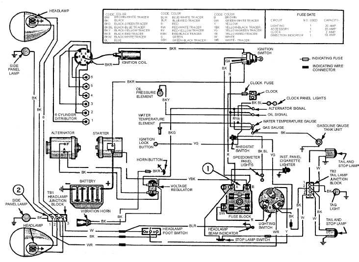
A wiring diagram is a detailed diagram of each circuit installation showing all of the wiring,
connectors, terminal boards, and electrical or electronic components of the circuit. It also identifies the
wires by wire numbers or color coding. Wiring diagrams are necessary to troubleshoot and repair
electrical or electronic circuits. The wiring diagram for an automobile is shown in figure 3-11. It shows
all the electrical components and that the interconnecting wiring is color coded.
Figure 3-11.—Wiring diagram.
You should use the schematic diagram previously discussed to determine where the trouble might be
in the circuit when a malfunction occurs. The schematic diagram does not show the terminals, connector
points, and so forth, of the circuit. Therefore, you must go to the circuit wiring diagram to determine
where to make the voltage or resistance checks in the circuit when troubleshooting. Following is an
example of how to use a schematic diagram in conjunction with a wiring diagram to troubleshoot a
circuit.
In the discussion of schematic diagrams, you will recall that when the light switch is pulled to the
PARK position, the tail lights, side panel lights, tag light, and the instrument lights come on. Now,
suppose that when the light switch is pulled to the PARK position all the lights come on, except the tag