1-17
AMMETER CONNECTED IN SERIES
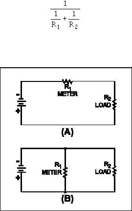
In figure 1-19(A), R1 and R2 are in series. The total circuit resistance is R2 + R2 and total circuit
current flows through both resistors. In figure 1-19(B), R1 and R2 are in parallel. The total circuit
resistance is
and total circuit current does not flow through either resistor.
Figure 1-19.—A series and a parallel circuit.
If R1 represents an ammeter, the only way in which total circuit current will flow through the meter
(and thus be measured) is to have the meter (R1) in series with the circuit load (R2), as shown in figure
1-19(A).
In complex electrical circuits, you are not always concerned with total circuit current. You may be
interested in the current through a particular component or group of components. In any case, an ammeter
is always connected in series with the circuit you wish to test. Figure 1-20 shows various circuit
arrangements with the ammeter(s) properly connected for measuring current in various portions of the
circuit.