1-21
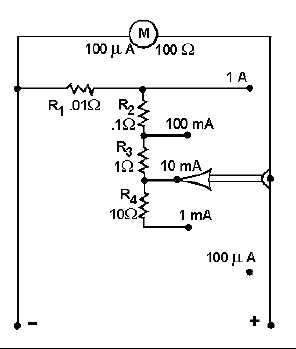
Figure 1-22.—An ammeter with internal shunt resistors.
By adding several shunt resistors in the meter case, with a switch to select the desired resistor, the
ammeter will be capable of measuring several different maximum current readings or ranges.
Most meter movements in use today have sensitivities of from 5 microamperes to 1 milliampere.
Figure 1-22 shows the circuit of meter switched to higher ranges, the shunt an ammeter that uses a meter
movement with a sensitivity of 100 microamperes and shunt resistors. This ammeter has five ranges (100
microamperes; 1, 10, and 100 milliamperes; 1 ampere) selected by a switch.
With the switch in the 100 microampere position, all the current being measured will go through the
meter movement. None of the current will go through any of the shunt resistors. If the ammeter is
switched to the 1 milliampere position, the current being measured will have parallel paths of the meter
movement and all the shunt resistors (R1 , R2, R3, and R4). Now, only a portion of the current will go
through the meter movement and the rest of the current will go through the shunt resistors. When the
meter is switched to the 10-milliampere position (as shown in fig. 1-22), only resistors R1, R2, and R3
shunt the meter. Since the resistance of the shunting resistance is less than with R4 in the circuit (as was
the case in the 1-milliampere position), more current will go through the shunt resistors and less current
will go through the meter movement. As the resistance decreases and more current goes through the shunt
resistors. As long as the current to be measured does not exceed the range selected, the meter movement
will never have more than 100 microamperes of current through it.
Shunt resistors are made with close tolerances. That means if a shunt resistor is selected with a
resistance of .01 ohms (as R1 in fig. 1-22), the actual resistance of that shunt resistor will not vary from
that value by more than 1 percent. Since a shunt resistor is used to protect a meter movement and to allow
accurate measurement, it is important that the resistance of the shunt resistor is known very accurately.
Figure 1-22 represents an ammeter with internal shunts. The shunt resistors are inside the meter case
and selected by a switch. For limited current ranges (below 50 amperes), internal shunts are most often
employed.