1-25
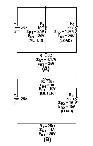
Figure 1-25.—Current and voltage in series and parallel circuits.
Figure 1-25(A) shows two resistors connected in parallel. Notice that the voltage across both
resistors is equal. In figure 1-25(B) the same resistors are connected in series. In this case, the voltage
across the resistors is not equal. If R1 represents a voltmeter, the only way in which it can be connected to
measure the voltage of R2 is in parallel with R2, as in figure 1-25(A).
LOADING EFFECT
A voltmeter has an effect on the circuit being measured. This is called LOADING the circuit. Figure
1-26 illustrates the loading effect and the way in which the loading effect is kept to a minimum.