1-30
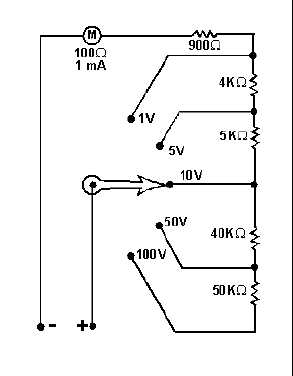
Figure 1-29.—A voltmeter with internal range resistors.
The current through the meter movement is determined by the voltage being measured. If the voltage
measured is higher than the range of the voltmeter, excess current will flow through the meter movement
and the meter will be damaged. Therefore, you should always start with the highest range of a voltmeter
and switch the ranges until a reading is obtained near the center of the scale. Figure 1-30 illustrates these
points.