2-20
Zener Diode Test
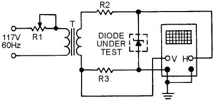
An audio signal generator may not be able to produce a high enough voltage for you to test Zener
diodes. You can, however, make this test with a diode test set or with the circuit shown in figure 2-10. In
this circuit, R1 is used to adjust the input voltage to a suitable value for the Zener diode being tested.
Resistor R2 limits the current through the diode. The signal voltage applied to the diode is also connected
to the horizontal input of the oscilloscope. The voltage developed across current-measuring resistor R3 is
applied to the vertical input of the oscilloscope. The horizontal sweep will therefore represent the applied
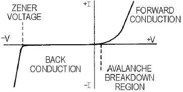
voltage, and the vertical deflection will indicate the current through the diode under test. Figure 2-11
shows the characteristic pattern of a Zener diode (note the sharp increase in current at the avalanche
breakdown point). For the Zener diode to be acceptable, this voltage must be within the limits specified
by the manufacturer.
Figure 2-10.—Zener diode test circuit.
Figure 2-11.—Zener diode characteristic pattern.
STATIC RESISTANCE MEASUREMENTS
One convenient method of testing a diode requires only your ohmmeter. The forward and back
resistances can be measured at a voltage determined by the battery potential of the ohmmeter and the
resistance range at which the meter is set. When the test leads of the ohmmeter are connected to the diode,
a resistance will be measured that is different from the resistance indicated if the leads are reversed. The
smaller value is called the forward resistance, and the larger value is called the back resistance. If the ratio
of back-to-forward resistance is greater than 10 to 1, the diode should be capable of functioning as a
rectifier. This is a very limited test, which does not take into account the action of the diode at voltages of


