3-18
If a dipole is used as the source of radiation, there will be radiation from the antenna into space
(dotted lines in figure 3-17) as well as toward the reflector. Energy that is not directed toward the
paraboloid has a wide-beam characteristic that would destroy the narrow pattern from the parabolic
reflector. This occurrence is prevented by the use of a hemispherical shield (not shown) that directs most
radiation toward the parabolic surface. By this means, direct radiation is eliminated, the beam is made
sharper, and power is concentrated in the beam. Without the shield, some of the radiated field would leave
the radiator directly. Since it would not be reflected, it would not become a part of the main beam and
thus could serve no useful purpose. The same end can be accomplished through the use of a PARASITIC
array, which directs the radiated field back to the reflector, or through the use of a feed horn pointed at the
paraboloid.
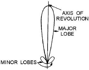
The radiation pattern of a parabola contains a major lobe, which is directed along the axis of
revolution, and several minor lobes, as shown in figure 3-18. Very narrow beams are possible with this
type of reflector. View A of figure 3-19 illustrates the parabolic reflector.
Figure 3-18.—Parabolic radiation pattern.
Truncated Paraboloid
View B of figure 3-19 shows a horizontally truncated paraboloid. Since the reflector is parabolic in
the horizontal plane, the energy is focused into a narrow horizontal beam. With the reflector truncated, or
cut, so that it is shortened vertically, the beam spreads out vertically instead of being focused. Since the
beam is wide vertically, it will detect aircraft at different altitudes without changing the tilt of the antenna.
It also works well for surface search radars to overcome the pitch and roll of the ship.


