1-10
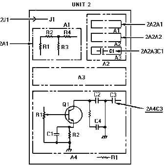
Figure 1-7.—Reference designations.
The first indicator, 2, is numeric and refers to unit 2. The next indicator, A2, is alphanumeric and
refers to assembly A2. The next indicator, A3, is also alphanumeric and refers to subassembly A3. The
last indicator, C1, like the two previous, is alphanumeric and refers to the part C1. We have just located
capacitor C1 on subassembly A3, which is on assembly A2, which is in unit 2 of the equipment.
Reference designations may be expanded or reduced to as many levels as required to identify a
particular part. Let's look at a couple of examples on our figure. The designator 2J1 identifies jack J1,
which is mounted directly on unit 2. The designator 2A4C3 identifies capacitor C3, which is on assembly
A4 in unit 2.
Partial reference designations are used to save space on diagrams. For example, refer back to figure
1-6. Partial reference designations are placed near the parts on subassembly A15, and a note indicates the
reference designation prefix is added. Capacitor C3 on subassembly A15 has the complete reference
designation 2A7A15C3.
Q7. A system is subdivided into what levels?
Q8. In the example 1A6CR3, what is the assembly designator?
NAVY FREQUENCY BAND USE
Rapid growth in the quantity and complexity of communications equipment and increased
worldwide international requirements for radio frequencies have placed large demands upon the radio-
frequency spectrum. These demands include military and civilian applications such as communications,
location and ranging, identification, standard time and frequency transmission, and industrial, medical,
and other scientific uses.
The allocation, assignment, and protection of all frequencies used by any component of the Navy are
the responsibility of Commander Naval Telecommunications Command (COMNAVTELCOM). Table


