2-18
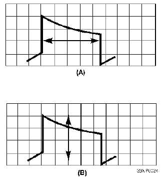
Figure 2-13.—Typical waveform displays.
The oscilloscope is also used to picture changes in quantities other than simply the voltages in
electric circuits. For example, if you need to see the changes in waveform of an electric current, you must
first send the current through a small resistor. You can then use the oscilloscope to view the voltage wave
across the resistor. Other quantities, such as temperatures, pressures, speeds, and accelerations, can be
translated into voltages by means of suitable transducers and then viewed on the oscilloscope. A detailed
discussion of the oscilloscope is presented in chapter 6 of this module.
USE OF THE SPECTRUM ANALYZER
The SPECTRUM ANALYZER is a device that sweeps over a band of frequencies to determine (1)
what frequencies are being produced by a specific circuit under test and (2) the amplitude of each
frequency component. To accomplish this, the spectrum analyzer first presents a pattern on a display.
Then the relative amplitudes of the various frequencies of the spectrum of the pattern are plotted (see
figure 2-14). On the vertical, or Y axis, the amplitudes are plotted; on the horizontal, or X axis, the
frequencies (time base) are plotted. The overall pattern of this display indicates the proportion of power
present at the various frequencies within the SPECTRUM (fundamental frequency with sideband
frequencies).

