2-21
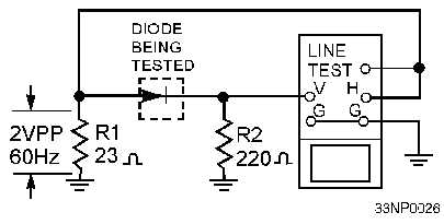
Figure 2-15.—Testing semiconductor diodes with an oscilloscope.
The test signal applied to the crystal diode is also connected to the horizontal input of the
oscilloscope. The horizontal sweep represents the voltage applied to the diode under test. The voltage
developed across current-measuring resistor R2 is applied to the vertical input of the oscilloscope.
Because this voltage is proportional to the current through the diode being tested, the vertical deflection
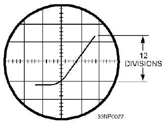
will indicate crystal current. The resulting oscilloscope trace for a normal diode is similar to the curve
shown in figure 2-16.
Figure 2-16.—Characteristic curve of a semiconductor diode.
To test Zener diodes, you must use a higher voltage than the oscilloscope line-test signal. This test
can be made with a diode test set or with the circuit shown in figure 2-17. In this circuit, rheostat R1 is
used to adjust the input voltage to a suitable value for the Zener diode being tested. Resistor R2 limits the
current through the diode. The signal voltage applied to the diode is also connected to the horizontal input
of the oscilloscope. The voltage developed across current-measuring resistor R3 is applied to the vertical
input of the oscilloscope. The horizontal sweep represents the applied voltage, and the vertical deflection
indicates the current through the diode being tested. Figure 2-18 shows the characteristic pattern of a
Zener diode. Note the sharp increase in current at the Zener voltage (avalanche) point. For the Zener
diode to be usable, this voltage must be within limits specified by the manufacturer.


