3-27
TECHNIQUES FOR METER USE
We have considered the more common meters; now let’s consider some of the techniques employed
in their use. The techniques suggested here are not all-inclusive. You will find, as you develop your
technical skills, other variations and techniques in use. Consider the techniques for measuring current in a
circuit. You can accomplish this by placing an ammeter in series with the circuit or by measuring the
voltage across a resistor of known value and using Ohm’s law to figure current. This last technique has the
advantage of eliminating the necessity of opening the circuit to connect the ammeter.
CONTINUITY TESTS
Open circuits are those in which the flow of current is interrupted by a broken wire, defective switch,
or any means by which the current cannot flow. The test used to detect open circuits (or to see if the
circuit is complete or continuous) is continuity testing.
An ohmmeter (which contains its own batteries) is excellent for use in a continuity test. Normally,
continuity tests are performed in circuits where the resistance is very low, such as the resistance of a
copper conductor. An open is indicated in these circuits by a very high or infinite resistance between two
continuously connected points.
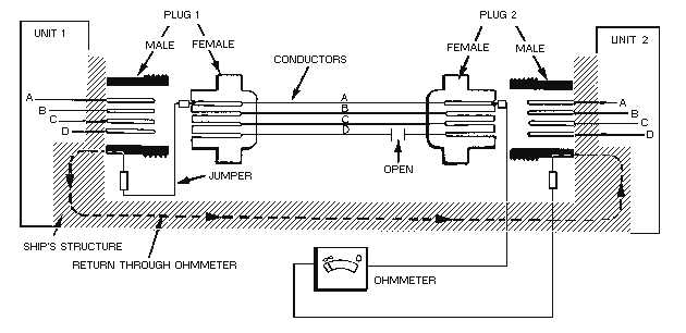
Figure 3-20 shows a continuity test of a cable that connects two electronic units. Notice that both
plugs are disconnected and the ohmmeter is in series with conductor D under test. The power should be
off. When checking conductors A, B, and C (connection of ohmmeter to conductors not shown), the
current from the ohmmeter flows through plug 2 (female) through conductor A, B, or C to plug 1
(female). From plug 1, current passes through the jumper to the chassis, which is "grounded" to the ship’s
structure. The metal structure serves as the return path to the chassis of unit 2 and completes the circuit
through the series-connected ohmmeter. The ohmmeter indicates a low resistance because no break exists
in conductors A, B, or C. However, checking conductor D reveals an open. The ohmmeter is shown
indicating maximum resistance because current cannot flow in an open circuit. With an open circuit, the
ohmmeter needle is all the way to the left since it is a series-type ohmmeter (reads right to left).
Figure 3-20.—Continuity test.


