3-23
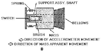
Figure 3-22B.—Pulse counting accelerometer.
When velocity remains constant, the brush spring holds the mass at null, and the brush rests on the
reset contact of the switch. As acceleration occurs, the tendency of the mass to remain at a constant
velocity causes the spring to compress. As the spring compresses, it allows the brush to move off the reset
contact. If the acceleration is great enough, the brush will pass over the switch contacts for acceleration
levels 1, 2, 3, and 4. These levels are determined by the stiffness of the spring.
As the brush passes over each contact (in a positive direction), an output pulse from each contact is
coupled to one of four counters. This advances the counter one-half count. The accelerometer is designed
so that as acceleration decreases, the mass tends to assume the new velocity. The counters will not
advance the remaining half count until the brush once again touches the reset contact. With this type of
pulse output, it is possible to record each time gravity forces have reached a predetermined level.
Q-21. Operation of an accelerometer is based on what physical property?
Q-22. What type of systems primarily use accelerometers?
Q-23. What special requirement is the pulse counting accelerometer designed for?
SUMMARY
In this chapter you were introduced to the subject of gyros. You studied the characteristics of gyros
and several applications of their use. You were also briefly introduced to the subject of accelerometers.
The following information provides a summary of the chapter.
The term GYROSCOPE (or GYRO) may be applied to any rapidly spinning object; however, a
functional gyroscope is constructed and mounted to take advantage of certain characteristics.


