3-22
Refer to figure 3-21. Notice that when there is no acceleration, the pendulum remains centered and
the accelerometer output is zero. However, when there is acceleration the mass or pendulum swings in the
direction opposite to that of the acceleration, causing an output from the E-transformer. Since the
amplitude of the pendulum's swing is proportional to the amplitude of the acceleration to which it is
subjected, the output of the device indicates both the direction and amplitude of the acceleration. This
output is within the limits of the equipment and is limited by physical stops.
PULSE-COUNTING ACCELEROMETER
The outputs of the accelerometers discussed so far are voltages, which are proportional to
acceleration. These voltages are assigned scale factors (such as units per volt). The voltage represents the
quantity. In many applications there is need for accelerometer output signals to be in digital form, which
means that the signal consists of a series of pulses that indicates an actual number. Pulse counting
accelerometers satisfy this need. Their pulse output can be supplied directly to computer circuits and other
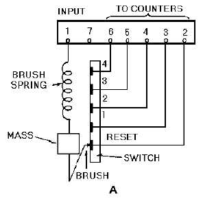
digital logic equipment. A schematic and a pictorial diagram of a pulse counting accelerometer is shown
in figure 3-22, view (A) and view (B).
Figure 3-22A.—Pulse counting accelerometer.


