1-11
is referred to as the MODULATED WAVE and is the waveform that is transmitted through space. When
the modulated wave is received and demodulated, the original component waves (carrier and modulating
waves) are reproduced with their respective frequencies, phases, and amplitudes unchanged.
Modulation of a carrier can be achieved by any of several methods. Generally, the methods are
named for the sine-wave characteristic that is altered by the modulation process. In this module, you will
study AMPLITUDE MODULATION, which includes CONTINUOUS-WAVE MODULATION. You
will also learn about two forms of ANGLE MODULATION (FREQUENCY MODULATION and
PHASE MODULATION). A special type of modulation, known as PULSE MODULATION, will also be
discussed. Before we present the methods involved in developing modulation, you need to study a process
that is essential to the modulation of a carrier, known as heterodyning.
To help you understand the operation of heterodyning circuits, we will begin with a discussion of
LINEAR and NONLINEAR devices. In linear devices, the output rises and falls directly with the input. In
nonlinear devices, the output does not rise and fall directly with the input.
LINEAR IMPEDANCE
Whether the impedance of a device is linear or nonlinear can be determined by comparing the
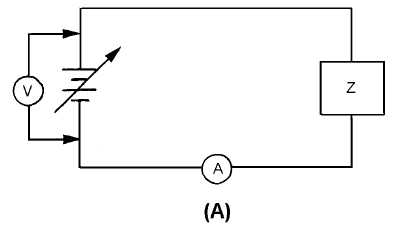
change in current through the device to the change in voltage applied to the device. The simple circuit
shown in view (A) of figure 1-4 is used to explain this process.
Figure 1-4A.—Circuit with one linear impedance.
First, the current through the device must be measured as the voltage is varied. Then the current and
voltage values can be plotted on a graph, such as the one shown in view (B), to determine the impedance
of the device. For example, assume the voltage is varied from 0 to 200 volts in 50-volt steps, as shown in
view (B). At the first 50-volt point, the ammeter reads 0.5 ampere. These ordinates are plotted as point a
in view (B). With 100 volts applied, the ammeter reads 1 ampere; this value is plotted as point b. As these
steps are continued, the values are plotted as points c and d. These points are connected with a straight
line to show the linear relationship between current and voltage. For every change in voltage applied to
the device, a proportional change occurs in the current through the device. When the change in current is
proportional to the change in applied voltage, the impedance of the device is linear and a straight line is
developed in the graph.


