2-22
PHASE MODULATION
Frequency modulation requires the oscillator frequency to deviate both above and below the carrier
frequency. During the process of frequency modulation, the peaks of each successive cycle in the
modulated waveform occur at times other than they would if the carrier were unmodulated. This is
actually an incidental phase shift that takes place along with the frequency shift in fm. Just the opposite
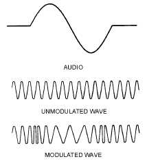
action takes place in phase modulation. The af signal is applied to a PHASE MODULATOR in pm. The
resultant wave from the phase modulator shifts in phase, as illustrated in figure 2-17. Notice that the time
period of each successive cycle varies in the modulated wave according to the audio-wave variation.
Since frequency is a function of time period per cycle, we can see that such a phase shift in the carrier will
cause its frequency to change. The frequency change in fm is vital, but in pm it is merely incidental. The
amount of frequency change has nothing to do with the resultant modulated wave shape in pm. At this
point the comparison of fm to pm may seem a little hazy, but it will clear up as we progress.
Figure 2-17.—Phase modulation.
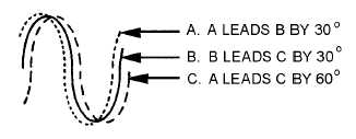
Let’s review some voltage phase relationships. Look at figure 2-18 and compare the three voltages
(A, B, and C). Since voltage A begins its cycle and reaches its peak before voltage B, it is said to lead
voltage B. Voltage C, on the other hand, lags voltage B by 30 degrees. In phase modulation the phase of
the carrier is caused to shift at the rate of the af modulating signal. In figure 2-19, note that the
unmodulated carrier has constant phase, amplitude, and frequency. The dotted wave shape represents the
modulated carrier. Notice that the phase on the second peak leads the phase of the unmodulated carrier.
On the third peak the shift is even greater; however, on-the fourth peak, the peaks begin to realign phase
with each other. These relationships represent the effect of 1/2 cycle of an af modulating signal. On the
negative alternation of the af intelligence, the phase of the carrier would lag and the peaks would occur at
times later than they would in the unmodulated carrier.
Figure 2-18.—Phase relationships.