1-37
Waveguide Plumbing
Since waveguides are really only hollow metal pipes, the installation and the physical handling of
waveguides have many similarities to ordinary plumbing. In light of this fact, the bending, twisting,
joining, and installation of waveguides is commonly called waveguide plumbing. Naturally, waveguides
are different in design from pipes that are designed to carry liquids or other substances. The design of a
waveguide is determined by the frequency and power level of the electromagnetic energy it will carry.
The following paragraphs explain the physical factors involved in the design of waveguides.
WAVEGUIDE BENDS.—The size, shape, and dielectric material of a waveguide must be constant
throughout its length for energy to move from one end to the other without reflections. Any abrupt change
in its size or shape can cause reflections and a loss in overall efficiency. When such a change is necessary,
the bends, twists, and joints of the waveguides must meet certain conditions to prevent reflections.
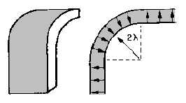
Waveguides may be bent in several ways that do not cause reflections. One way is the gradual bend
shown in figure 1-46. This gradual bend is known as an E bend because it distorts the E fields. The E
bend must have a radius greater than two wavelengths to prevent reflections.
Figure 1-46.—Gradual E bend.
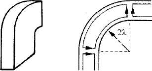
Another common bend is the gradual H bend (figure 1-47). It is called an H bend because the H
fields are distorted when a waveguide is bent in this manner. Again, the radius of the bend must be greater
than two wavelengths to prevent reflections. Neither the E bend in the "a" dimension nor the H bend in
the "b" dimension changes the normal mode of operation.
Figure 1-47.—Gradual H bend.
A sharp bend in either dimension may be used if it meets certain requirements. Notice the two
45-degree bends in figure 1-48; the bends are 1/4! apart. The reflections that occur at the 45-degree bends
cancel each other, leaving the fields as though no reflections have occurred.


