1-63
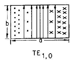
description of the various TE and TM modes. The dominant mode for rectangular waveguides is shown in
the figure.
WAVEGUIDE INPUT/OUTPUT METHODS are divided into three basic categories: PROBES,
LOOPS, and SLOTS. Size, shape, and placement in the waveguide are critical factors in the efficiency of
all three input/output methods.
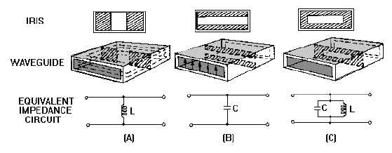
WAVEGUIDE/IMPEDANCE MATCHING is often necessary to reduce reflections caused by a
MISMATCH between the waveguide and the load. Matching devices called IRISES, shown in the
illustration, are used to introduce either capacitance or inductance (or a combination of both) into a
waveguide. Conductive POSTS and SCREWS can also be used for impedance matching in waveguides.
WAVEGUIDE TERMINATIONS prevent standing waves at the end of a waveguide system. They
are usually specially constructed HORNS or absorptive loads called DUMMY LOADS.
WAVEGUIDE PLUMBING refers to the bends, twists, and joints necessary to install waveguides.
E bends, H bends, and twists must have a radius greater than two wavelengths. The CHOKE JOINT,
shown in the figure, is most often used to connect two pieces of waveguide. The ROTATING JOINT is
used when a waveguide must be connected to a rotating load such as an antenna.


