1-16
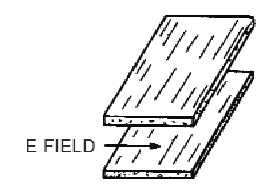
Figure 1-19B.—E field boundary condition. DOES NOT MEET BOUNDARY CONDITIONS.
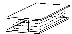
The second boundary condition, which is illustrated in figure 1-20, can be stated as follows:
For a varying magnetic field to exist, it must form closed loops in parallel with the conductors and be
perpendicular to the electric field.
Figure 1-20.—H field boundary condition.
Since an E field causes a current flow that in turn produces an H field, both fields always exist at the
same time in a waveguide. If a system satisfies one of these boundary conditions, it must also satisfy the
other since neither field can exist alone. You should briefly review the principles of electromagnetic
propagation in free space (NEETS, Module 10, Introduction to Wave Propagation, Transmission Lines,
and Antennas). This review will help you understand how a waveguide satisfies the two boundary
conditions necessary for energy propagation in a waveguide.
WAVEFRONTS WITHIN A WAVEGUIDE.—Electromagnetic energy transmitted into space
consists of electric and magnetic fields that are at right angles (90 degrees) to each other and at right
angles to the direction of propagation. A simple analogy to establish this relationship is by use of the
right-hand rule for electromagnetic energy, based on the POYNTING VECTOR. It indicates that a screw
(right-hand thread) with its axis perpendicular to the electric and magnetic fields will advance in the
direction of propagation if the E field is rotated to the right (toward the H field). This rule is illustrated in
figure 1-21.


