3-14
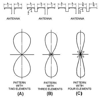
consisting of two horizontally mounted elements, each a half wavelength long and fed in phase. The
resulting radiation pattern is in a direction at right angles to the plane containing the antenna conductor.
Figure 3-14.—Horizontal array field patterns.
Three- and four-element arrays are shown in figure 3-14, views (B) and (C), respectively. The field
pattern of each array is shown beneath it. Note that the beam becomes sharper as the number of elements
is increased. If a still-narrower beam is desired, you may add additional elements. The field patterns of the
antennas in the figure are bidirectional. Unidirectional patterns may be obtained with a parasitic reflector
mounted behind the driven antenna elements.
The BEDSPRING ARRAY (figure 3-15), so called because of its resemblance to a bedspring, is an
example of a unidirectional antenna. It consists of a stacked dipole array with an untuned reflector. The
more dipoles that are used or stacked in one dimension (horizontal, for example), the more narrow the
beam of radiated energy becomes in that plane. Consequently, the size of the antenna is not the same for
all installations. Antennas such as the bedspring array are commonly used in TWO-DIMENSIONAL
SEARCH RADARS that obtain the range and bearing information of a target.


