3-25
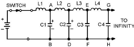
Figure 3-23.—Dc applied to an equivalent transmission line.
Since none of the charge is lost, the total charge leaving the battery during T is equal to the total
charge on the line. Therefore:
Q = IT = CE
As each capacitor accumulates a charge equal to CE, the voltage across each inductor must change.
As C1 in figure 3-23 charges to a voltage of E, point A rises to a potential of E volts while point B is still
at zero volts. This makes E appear across L2. As C2 charges, point B rises to a potential of E volts as did
point A. At this time, point B is at E volts and point C rises. Thus, we have a continuing action of voltage
moving down the infinite line.
In an inductor, these circuit components are related, as shown in the formula
This shows that the voltage across the inductor is directly proportional to inductance and the change
in current, but inversely proportional to a change in time. Since current and time start from zero, the
change in time (DT) and the change in current (DI) are equal to the final time (T) and final current (I). For
this case the equation becomes:
ET = LI
If voltage E is applied for time (T) across the inductor (L), the final current (I) will flow. The
following equations show how the three terms (T, L, and C) are related:
For convenience, you can find T in terms of L and C in the following manner. Multiply the left and
right member of each equation as follows:


