3-23
At the generator:
Rise from
-100 V to -70 V
At point W:
Drop from
0 V to -70 V
At point X:
Drop from
+100 V to +70 V
At point Y:
Rise from
0 V to + 70 V
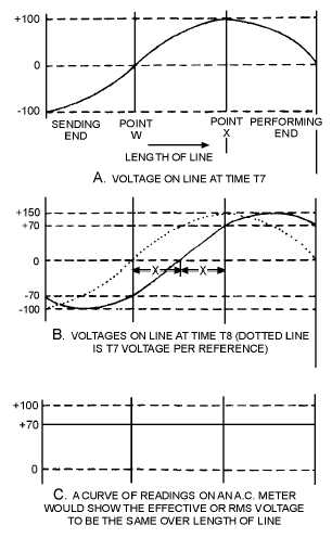
Figure 3-22.—Instantaneous voltages along a transmission line.
A plot of these new voltages produces the solid curve shown in figure 3-22, view B. For reference,
the curve from T7 is drawn as a dotted line. The solid curve has exactly the same shape as the dotted
curve, but has moved to the right by the distance X. Another plot at T9 would show a new curve similar
to the one at T8, but moved to the right by the distance Y.
By analyzing the points along the graph just discussed, you should be able to see that the actions
associated with voltage changes along an rf line are as follows:
1. All instantaneous voltages of the sine wave produced by the generator travel down the line in the
order they are produced.
2. At any point, a sine wave can be obtained if all the instantaneous voltages passing the point are
plotted. An oscilloscope can be used to plot these values of instantaneous voltages against time.


