4-2
simple facts in mind as you study limiters will help you understand their operation. Your knowledge of
voltage divider action from NEETS, Module 1, Introduction to Matter, Energy, and Direct Current will
also help you understand limiters.
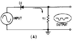
In a SERIES LIMITER, a diode is connected in series with the output, as shown in view (A) of
figure 4-1. The input signal is applied across the diode and resistor and the output is taken across the
resistor. The series-limiter circuit can limit either the positive or negative alternation, depending on the
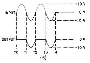
polarity of the diode connection with respect to ground. The circuit shown in figure 4-1, view (B), is a
SERIES-POSITIVE LIMITER. Reversing D1 would change the circuit to a SERIES-NEGATIVE
LIMITER.
Figure 4-1A.—Series-positive limiter.
Figure 4-1B.—Series-positive limiter.
Series-Positive Limiter
Let's look at the series-positive limiter and its outputs in figure 4-1. Diode D1 is in series with the
output and the output is taken across resistor R1. The input must be negative with respect to the anode of
the diode to make the diode conduct. When the positive alternation of the input signal (T0 to T1) is
applied to the circuit, the cathode is positive with respect to the anode. The diode is reverse biased and
will not conduct. Since no current can flow, no output is developed across the resistor during the positive
alternation of the input signal.
During the negative half cycle of the input signal (T1 to T2), the cathode is negative with respect to
the anode. This causes D1 to be forward biased. Current flows through R1 and an output is developed.


