1-36
the least amount of opposition is offered to the high frequencies by the capacitor, and most of the high-
frequency energy returns to the source through the capacitor.
HIGH-PASS FILTER
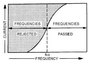
A high-pass filter circuit passes all currents having a frequency higher than a specified frequency,
while opposing all currents having a frequency lower than its specified frequency. This is illustrated in
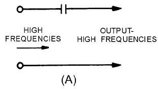
figure 1-17. A capacitor that is used in series with the source of both high and low frequencies, as shown
in view (A) of figure 1-18, will respond differently to high-frequency, low-frequency, and direct currents.
It will offer little opposition to the passage of high-frequency currents, great opposition to the passage of
low-frequency currents, and completely block direct currents. The value of the capacitor must be chosen
so that it allows the passage of all currents having frequencies above the desired value, and opposes those
having frequencies below the desired value. Then, in order to shunt the undesired low-frequency currents
back to the source, an inductor is used, as shown in view (B). This inductor must have a value that will
allow it to pass currents having frequencies below the frequency cutoff point, and reject currents having
frequencies above the frequency cutoff point, thus forcing them to pass through the capacitor. By
combining inductance and capacitance, as shown in view (C), you obtain the simplest type of high-pass
filter. At point P most of the high-frequency energy is passed on to the load by the capacitor, and most of
the low-frequency energy is shunted back to the source through the inductor.
Figure 1-17.—High-pass filter response curve.
Figure 1-18A.—Components of a simple high-pass filter.


